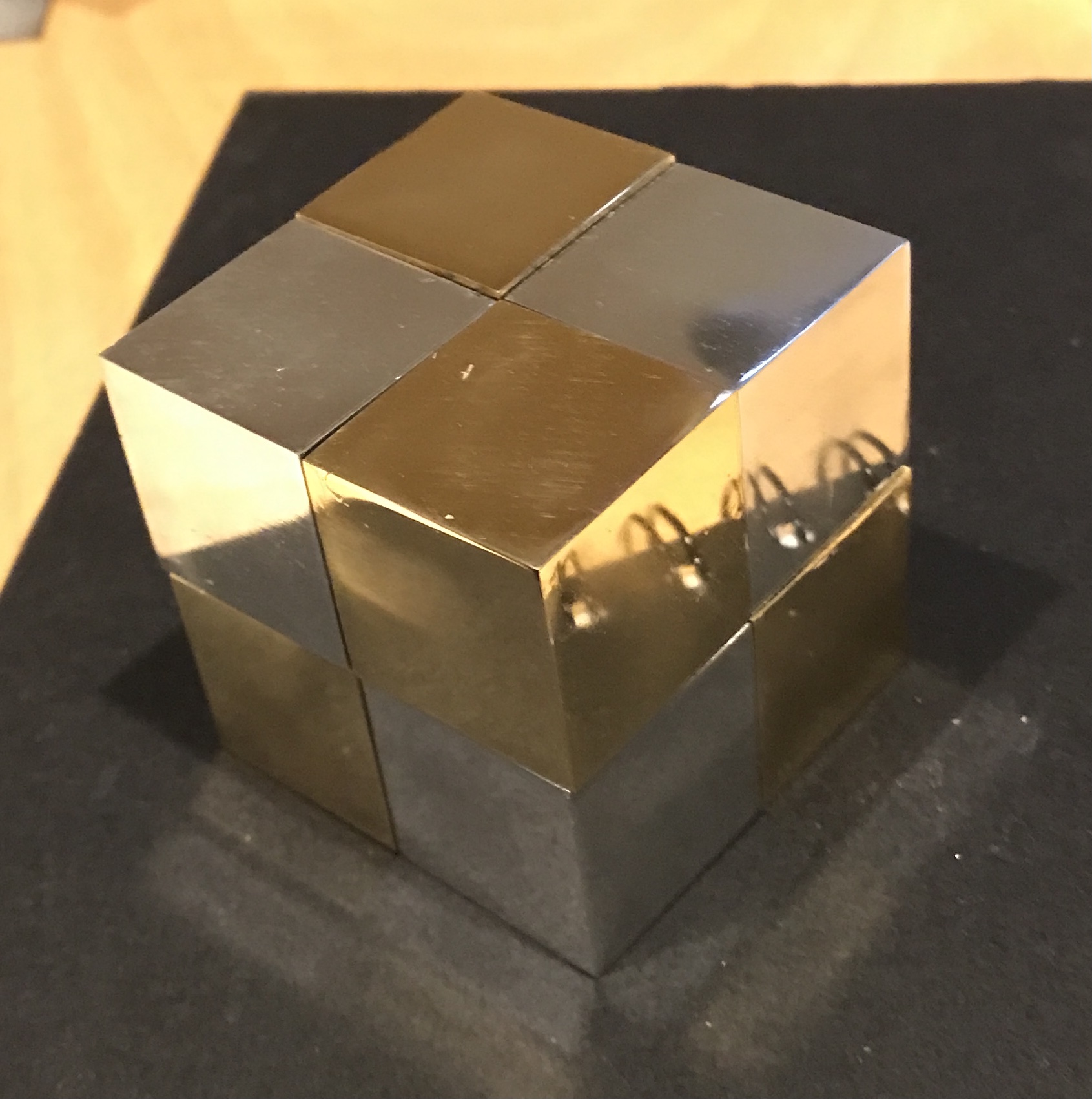
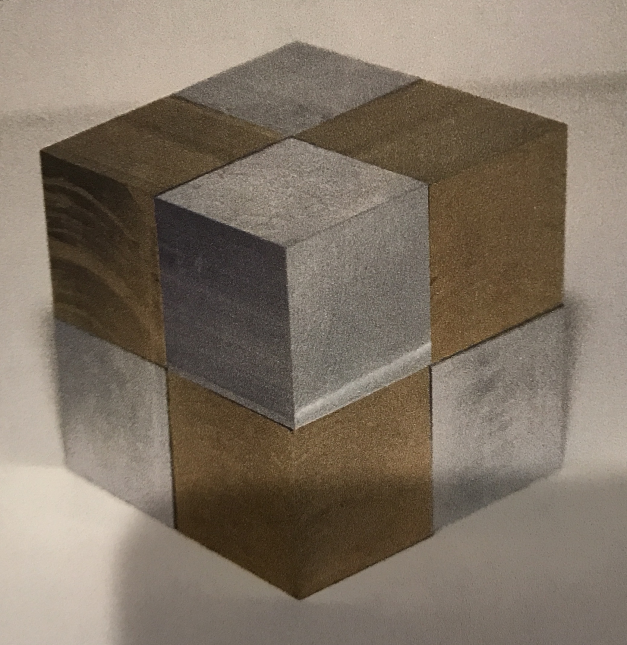
I decided to make another project from J. Randolph Bulgin's "Puzzles and Peculiarities from the Machine Shop". It is called the keyhole cube. Eight cubes of brass and aluminum have keyholes cut in one or two sides. One or two sides also have 'keys' attached. All eight cubes are unique. It is a puzzle requiring disassembly and assembly. His assembled cube is shown below.
Two one foot long 1.25" square bars of metal were ordered. They arrived yesterday. Looking at the bars this morning revealed that the brass bar was smaller than the aluminum bar. Sure enough it is 1.125" square. I was just about to mail Online Metals with my gripe, when I looked at the order. I ordered the brass in a slightly smaller size! I don't think the size matters as long as the two bars are the same. I guess I will be removing more aluminum than I expected.
Four cubes of each metal are required. At 1 1/8" square I need a 5" long bar. That gives me 1/2" of material for the cuts to separate the cubes. I will use the newly renovated band saw to cut the metal. We will see if it performs as well as it did on the test cut. Beautiful cuts, not perfectly square. I need to move the adjustable rollers in closer to the work.
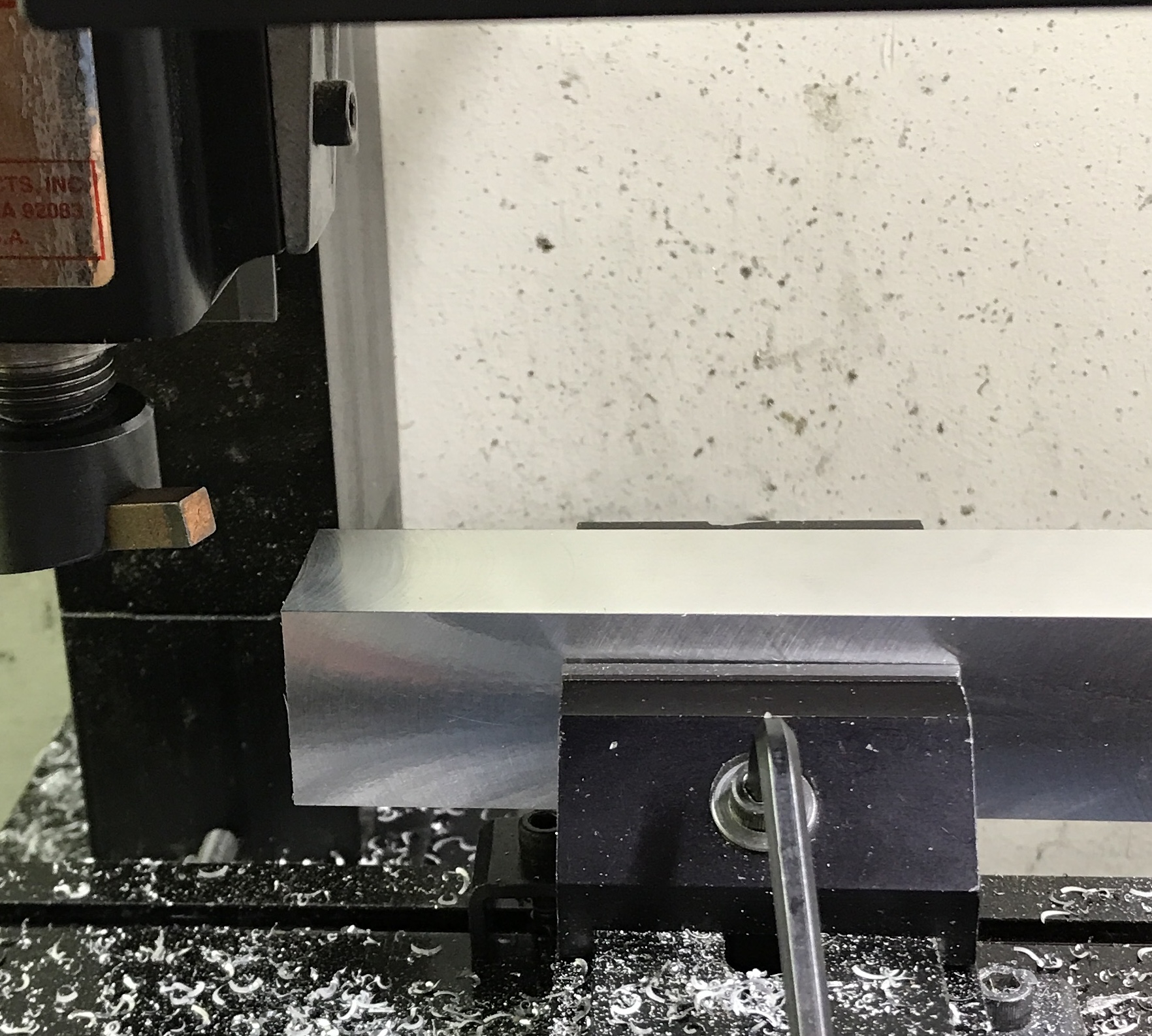
The brass bar is exactly 1.125" square. I plan to only sand the four outside faces. The aluminum needs to be milled. It is 1.252" square. I will mill 1/16" off of all four faces, so they are all pristine. I started with the fly cutter. I was only able to remove 0.005" in a pass. And that had to be taken very slowly. I will reserve the fly cutter for the finish cut. The South Bend lathe will be used to reduce the aluminum to 1.140" or so.
The block of aluminum was chucked in the four jaw chuck. It was turned at 300 rpm. The cuts went smoothly, throwing chips everywhere. One side had already been cut with the fly cutter, so only three sides were cut. The block of aluminum was returned to the mill and the fly cutter was used to clean the three lathe cut faces. The dimensions across the square cross section were reduced to 1.125" ±0.002".
Measure once and cut twice. Now I need to shrink the cubes even further. I am shooting for 1" cubes. A 1/4" end mill was too slow and may be dull. Switched to a 3/8" end mill. The cutting was much smoother, but back and forth across a cube face takes too long. Switched to the lathe. Works well. Requires a fly cutter afterward to produce a really nice face. It is difficult getting the cube square in the vise jaws with the aluminum protectors. The aluminum cubes were reduced to almost one inch on the South Bend lathe. I started reducing the size of the brass cubes on the Sherline. It takes longer than the South Bend as expected. Switched to the South Bend and the brass cubes were reduced to slightly over 1.000", so the sides could finished with the fly cutter. Most of the cubes were finished with the fly cutter. When there was too little material to remove they were sanded up to 400 grit.
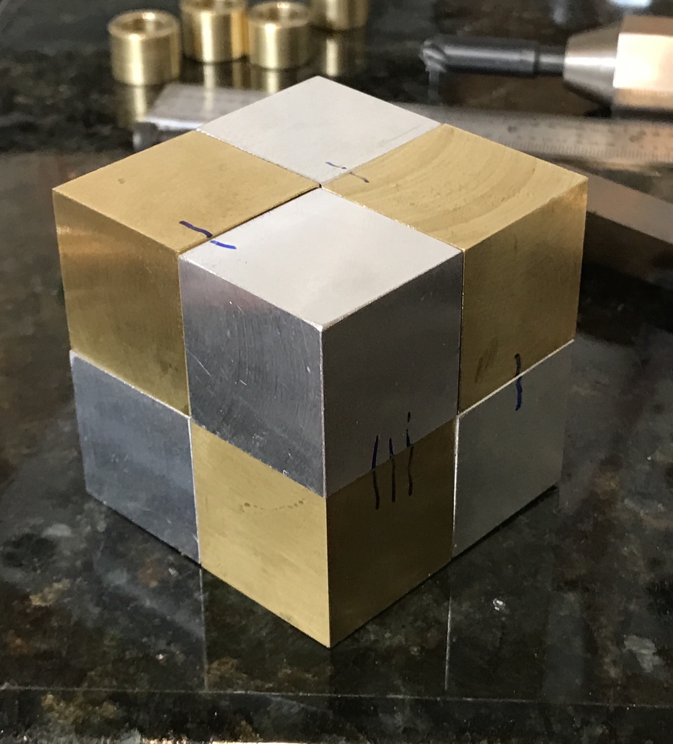
Each of the one inch cubes becomes a unique piece of the puzzle. Each has at least one button and at least one keyed slot. There are three face modifications on each cube. They occupy three adjacent faces. I will use the common corner as a reference for each modification. The corner with the three emanating edges closest to perpendicularity was selected and marked for each of the eight cubes. The three faces of the cubes were then marked for button or keyway as shown in the photo below. A problem raised its ugly head. The cubes are 1" and the keyway cutter is 1/2"!
There are three steps to milling the keyhole. The cube is repeatably secured in the vise and a 0.50" hole is drilled/milled into the cube 0.250" off of center. A 1/4" end mill is inserted and the slot is cut so the center of the end mill aligns with the center of the face. The resulting bump on the side of the circle is 1/8" deep. The keyway is then cut with careful attention to chip removal.
All of the buttons are centered on the face. The buttons are screwed onto a #10-32 stud screwed into the hole in the face. A repeatable setup is required to drill and tap the holes precisely in the center. The buttons themselves are mushroom shaped. They are 0.220" high. The cap is 0.120" high and 0.490" in diameter. The stem is 0.100" high and 0.240" in diameter. The stem is drilled and tapped for the #10-32 stud.
A smaller keyhole cutter was located on the internet. One can be purchased from a Japanese company, Misumi, in many metric sizes. A 10 mm (0.408") cutter with 3 mm (0.118") flute depth is $41.33 before shipping. Misumi has many warehouses in the US. Alternatively, I can try to make one from HSS.
The Misume keyhole cutter described above arrived yesterday. I am excited to get back to this project. Before milling I need to map out the new dimensions of the slots and the buttons. As measured the new keyhole cutter is 0.398" in diameter. The height of the cutting edges is 0.117". I don't know if my diameter measurement is somehow incorrect. The buttons will be made to fit.
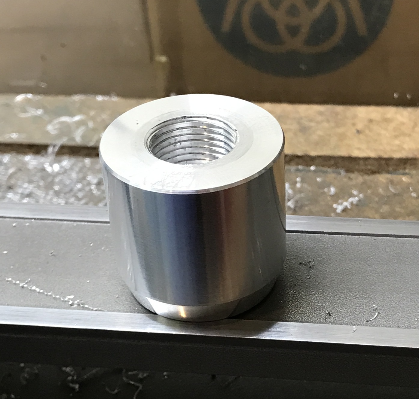
The process of milling the keyhole was first tried out on a scrap of aluminum. It was held in the vise and the edge and center were found. The table was moved 0.263" to put the spindle on center above the desired location. A hole was drilled with a center drill followed by a 3/16" drill to a depth of 0.179". The hole was then opened with a 3/8" drill (dull!). A 3/16" end mill was used to mill a slot that is 0.237" from the site of the drilled hole. The keyhole cutter was then used to open the keyhole and produce the slot. The shaft on the keyhole cutter is 10 mm, so a drill chuck was used to hold it. Drilling down went easily as a minimal amount of material was removed. Cutting the slot was straightforward, but slow. The slot was cut until the cutter reached the end of the slot milled earlier. The photo shows the milled keyhole.
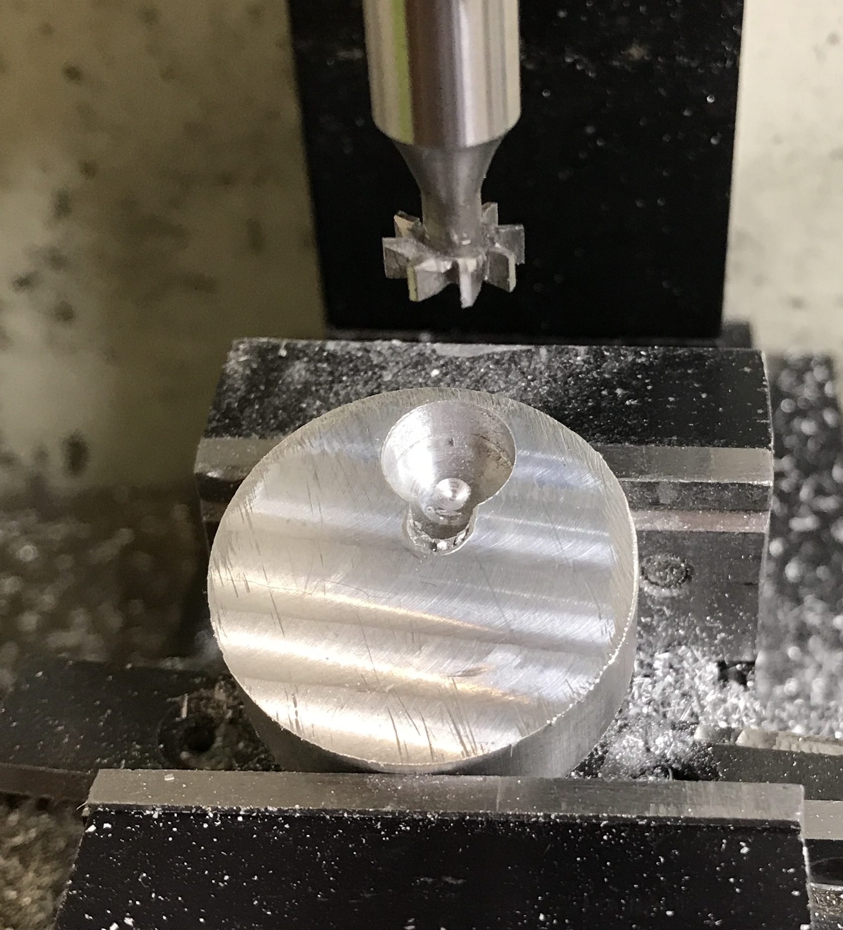
This was very difficult without a DRO. Even milling the slot with the 3/16" end mill was difficult as the the rotations of the handle had to be counted in both directions, while managing the backlash. In retrospect I don't believe the slot was cut far enough by about 0.050". A poor man's DRO is needed!
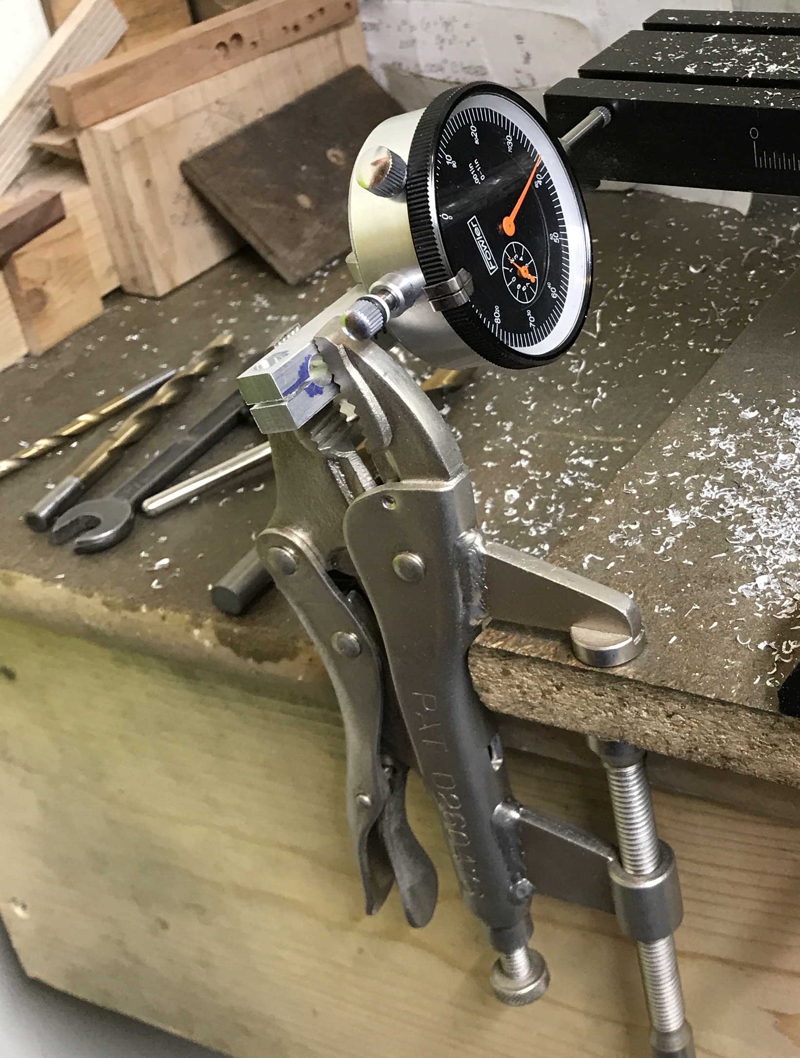
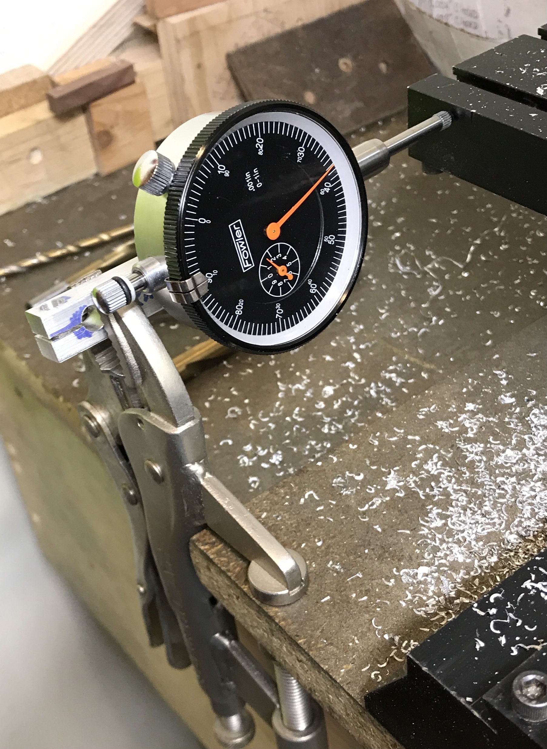
Simple enough to do if only one axis needs to be tracked as in this case. I remembered the vise-lock pliers on a clamp attached to a shelf in the garage. They were being used to hang my face shield. Now they have a real use. The bar for tramming was screwed to the dial gauge. This bar was clamped in the vise-lock pliers. The C-clamp was attached to the board holding the mill. This gave solid locks from the gauge to the table. Very positive movement on the gauge as the table is moved on the y-axis.
Followed the same procedure with a 1" aluminum cube. The vise was first checked to make sure it was aligned with the x-axis. It was almost perfect! The block was slid to the right in the vise until it was butted against a parallel held against the jaws. The right edge was located and the spindle was shifted to center. The back edge was located and the spindle was advanced on the y-axis 0.263".
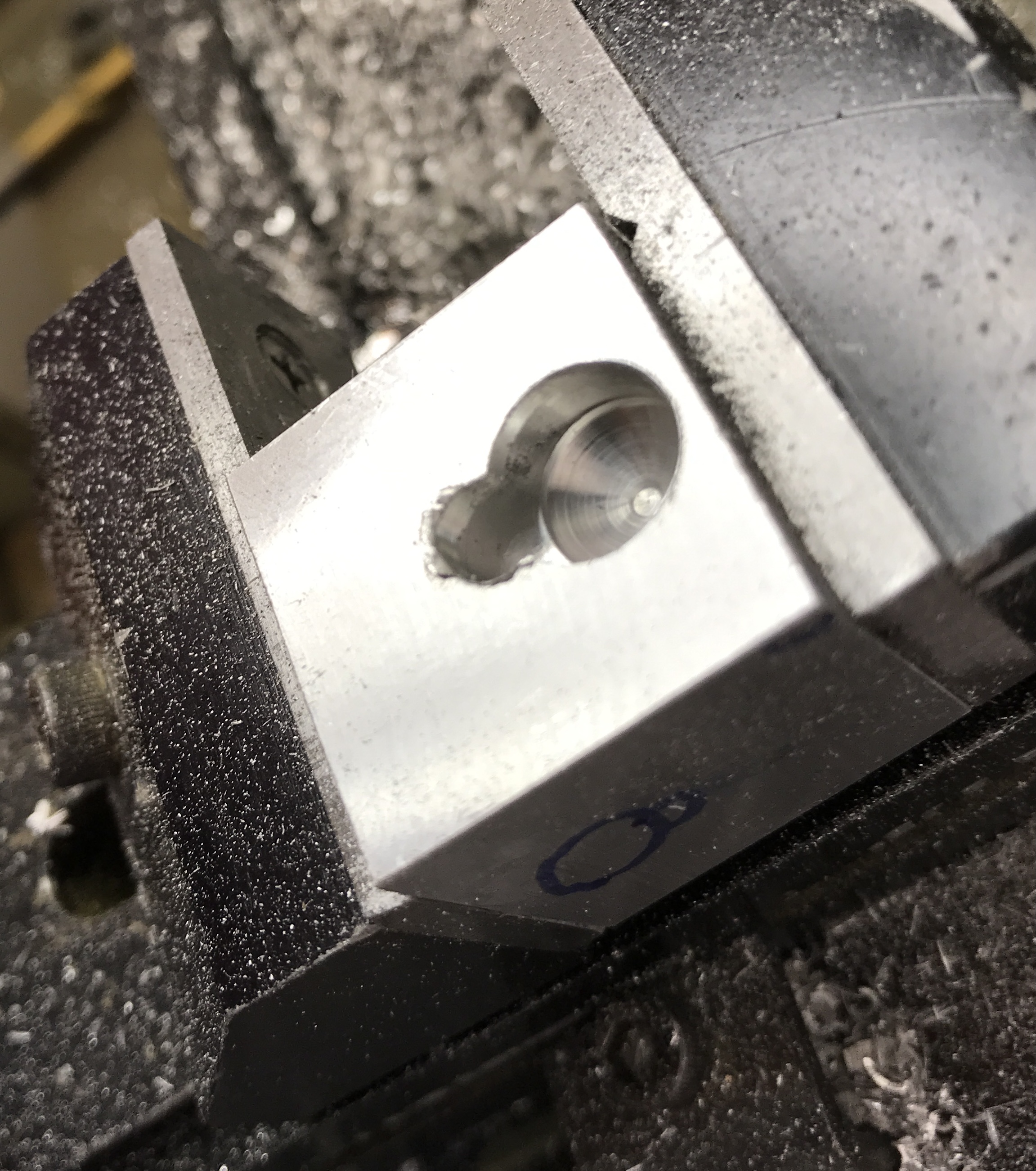
The only real challenge was drilling the hole to 3/8". Before using the drills they were stoned by hand. There was still tremendous chatter with the 3/8" drill and the table shifted about 0.015" on the x-axis! The x-axis was locked. This only affected milling the 3/16" slot and it was widened at the correct setting at the end. The keyhole cutter worked fine. The cutting was stopped a few times and the cutter backed out in order to blow out the chips. The following shot is an attempt to show the inside of the keyhole while the part is still in the vise.
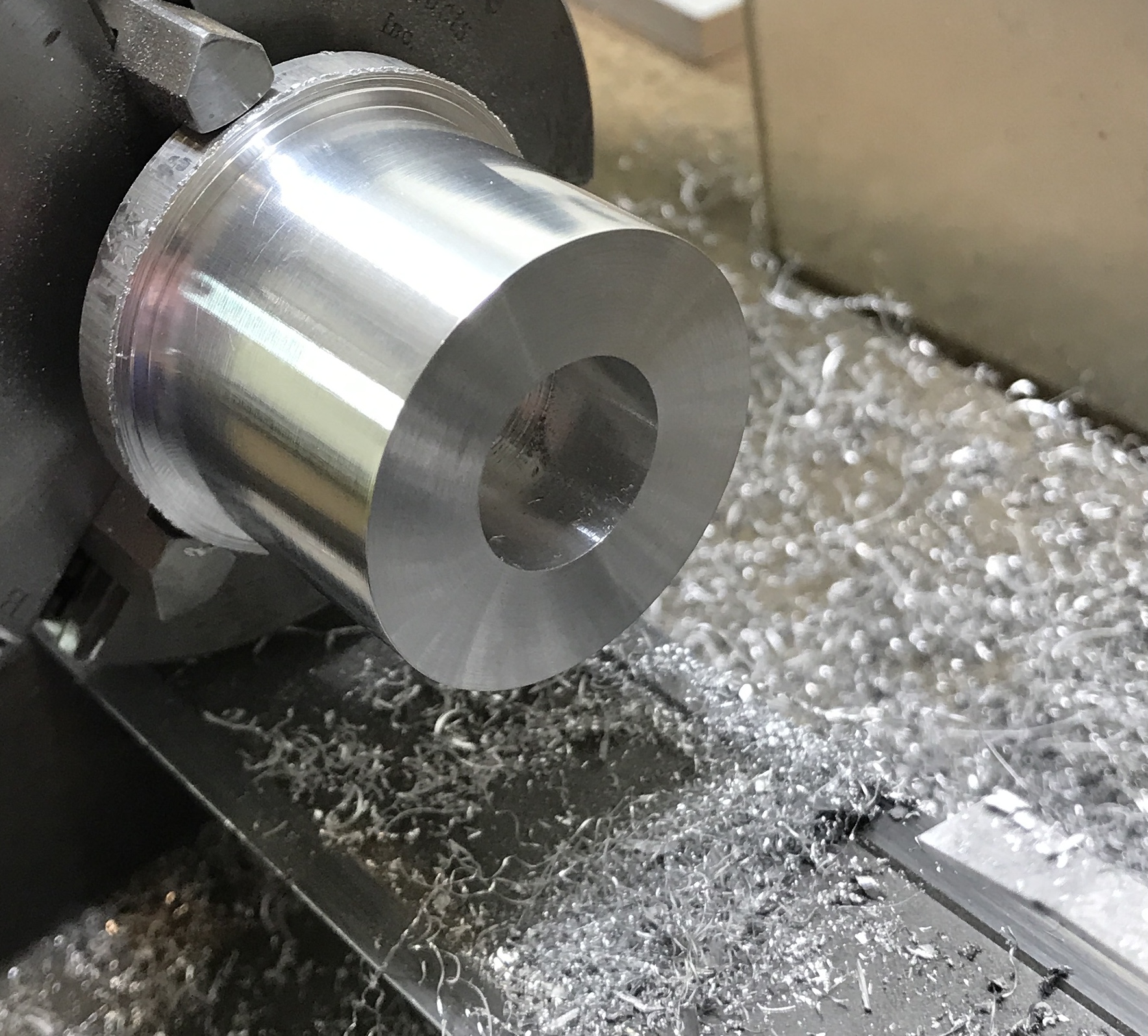
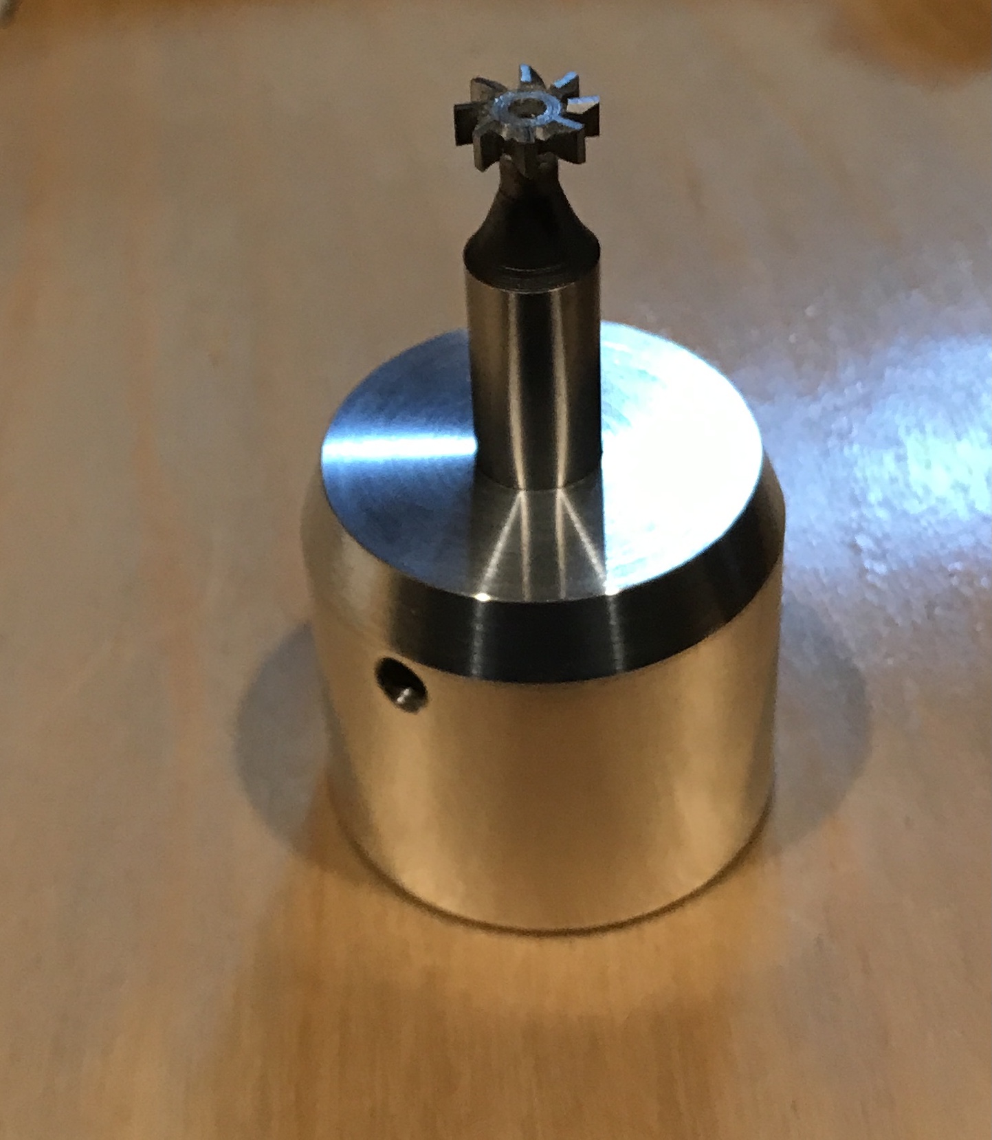
Stopped to make a collet to hold the 0.398" keyhole cutter. An overly large scrap of aluminum was turned down to 1.5" for 1.125". A 3/8" hole was drilled about 0.5" deep. This hole was then bored to 0.703" in preparation for cutting threads 0.047" deep. The threads were cut, but unfortunately a gear came loose about halfway. The resulting threads are less than spectacular. The fit on the headstock is acceptable. After removing the part from the chuck and screwing it onto the headstock the end was faced and drilled to 3/8". It was bored to a good fit on the 10 mm keyhole cutter. The end was tapered 20°. The collet was drilled with a #21 drill and then tapped 10-32. Three photos below document the process: bored, threaded, and completed.
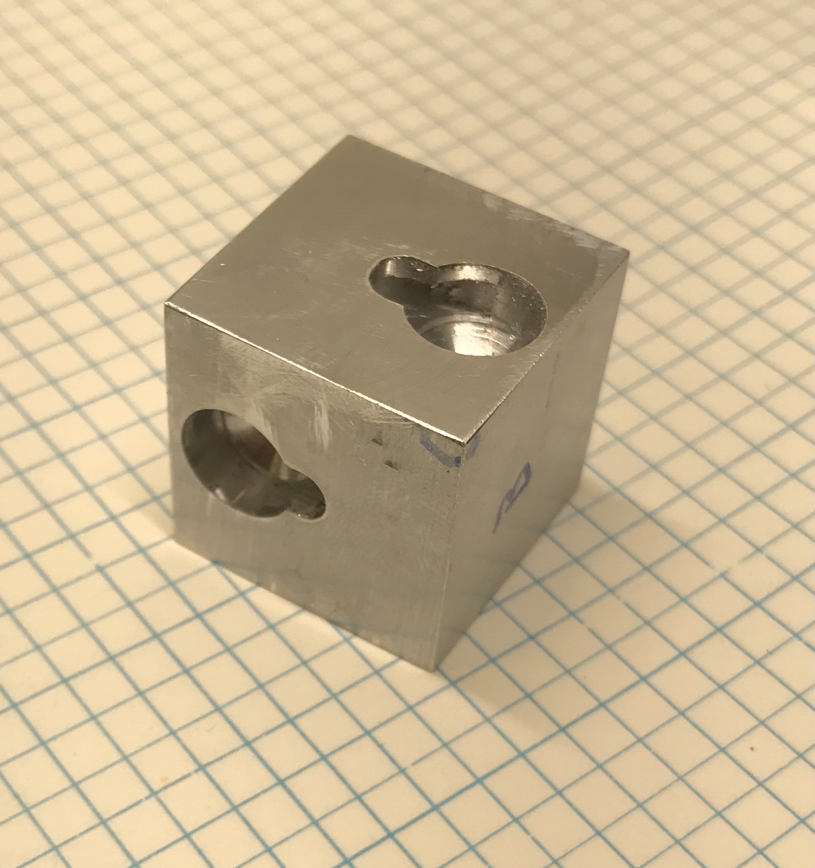
The second slot was cut this morning. It was on the opposite side of the block from the reference corner, so the dial gauge had to be moved. Everything went well including the drilling with a sharp 3/8" drill. The entire process is quite noisy so I stopped after completing only one more slot. I will work tomorrow morning, when Rhea is teaching dancing in the garage. The photo below shows the first aluminum block that just needs to be drilled and tapped for the button.
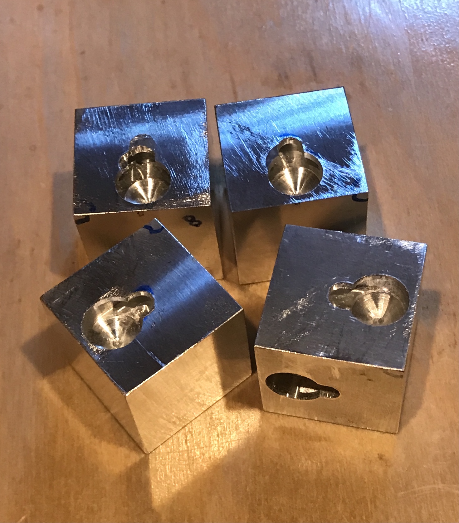
All five keyhole slots were prepared similarly in the aluminum. One slot was milled too far with the 3/16" end mill. An aluminum rod 3/16" X 0.190" was put in the end of the slot with a little Loctite. After drying the slot was milled to the correct dimensions. Unfortunately, the block came loose during the milling producing an obvious flaw!! (Slot in the back left corner.)
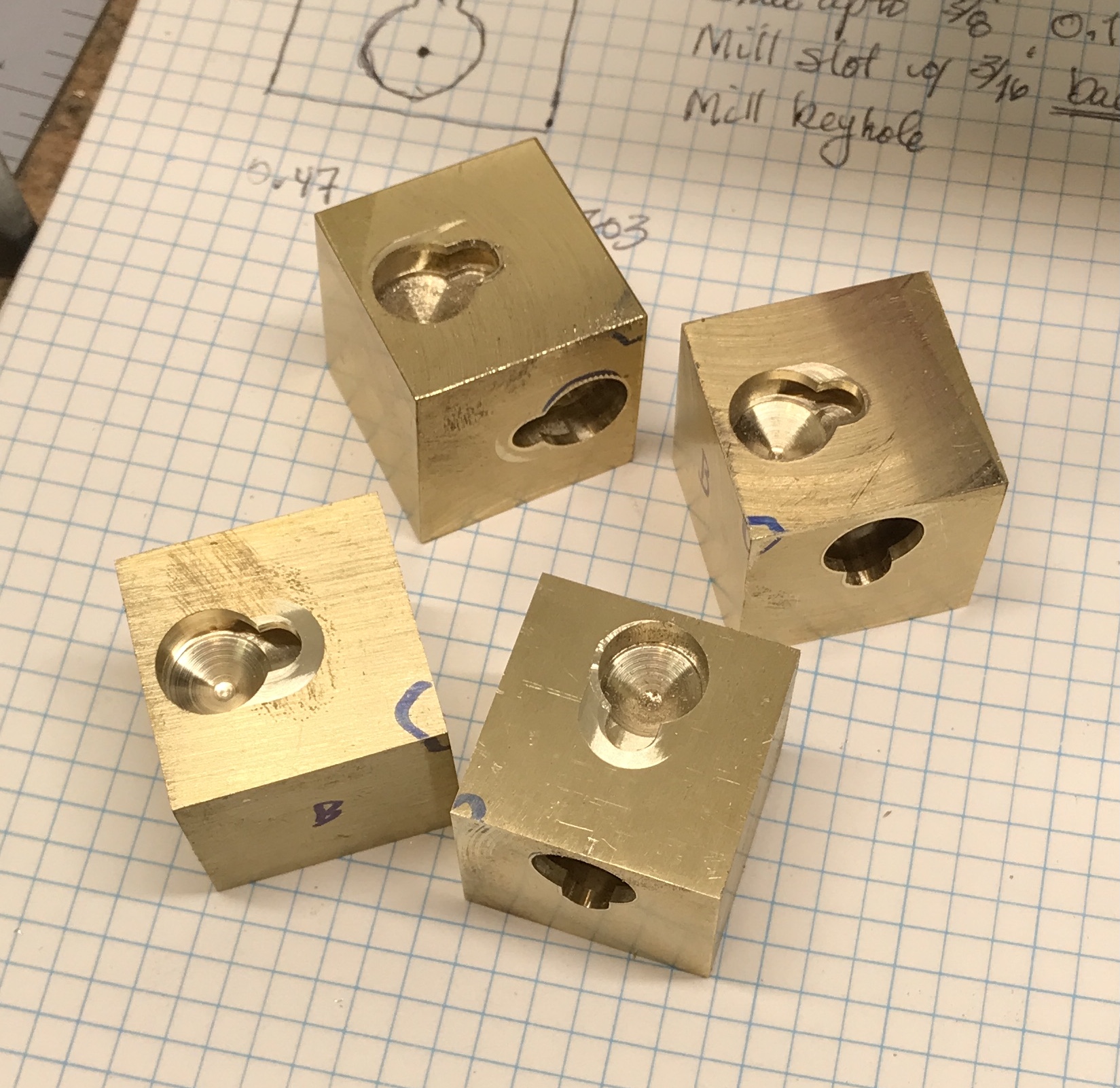
The brass was next with seven keyhole slots to make. Three were made this morning. All proceeded well. The brass seems to be more forgiving than the aluminum. Finished the rest on the following morning. The photo below shows the seven keyhole slots in the brass cubes.
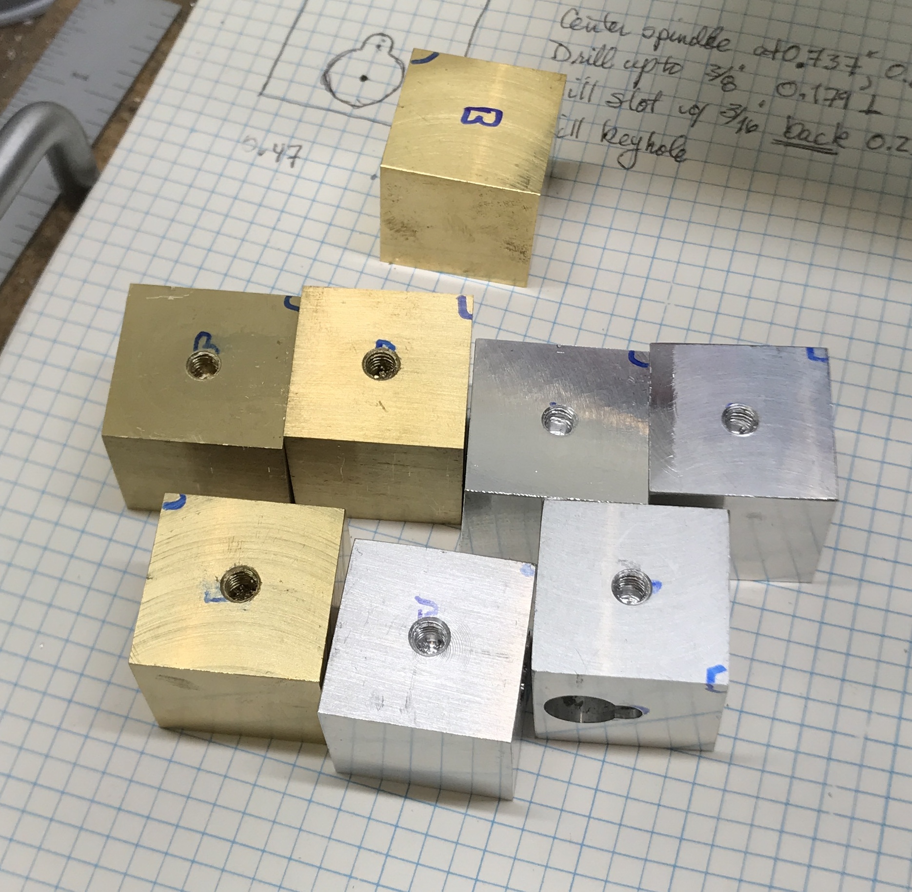
Drilling and tapping a dozen holes was next on the agenda. The marked edges of the blocks were located and the spindle centered over the block. The block was center drilled, drilled with a #21 drill, chamfered, and tapped 10-32. The first seven drilled and partially tapped holes are seen below.
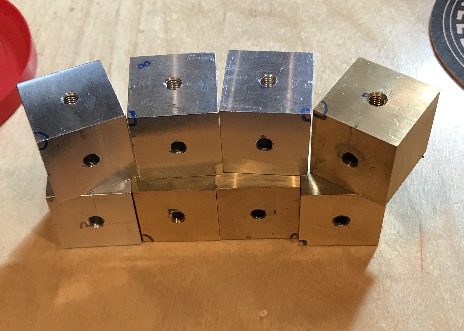
The last five holes were drilled and tapped the Wednesday before Thanksgiving. All twelve drilled and tapped holes are seen in the picture below.
The current plan for making the buttons is to make them in one piece on the lathe. The threads will be 0.25" long followed by an undercut, a 0.185" diameter neck, and the button 0.395" in diameter and 0.115" thick. The neck should be about 1/16" long, but the exact length will await some experimentation.
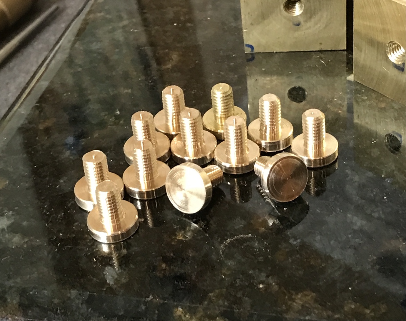
The first button was made and tested. The screw is slightly too long and the thickness of the button needs to be reduced. Production mode was started this morning. Bronze was used (1/2" rod) as that is what I have. A two inch length was cut off and placed in the three jaw chuck. It was faced and the diameter was reduced to 0.395" for 0.5" length. The first 5/16" was further reduced to 0.188". Thread relief was cut with two passes of the parting tool. Not really thread relief as the depth is only 0.005". But the relief is needed to fit in the slots. The end of the part was chamfered and the part was threaded 10-32. The button/screw was parted off at about 0.36". This was repeated 11 times. It was then necessary to adjust some of the dimensions. Mostly the thickness of the button needed reduction. The parts were held in the collet and trimmed up as needed to the following button dimensions: 0.100"" X 0.395". The buttons at this stage are shown below.
Caution!!! Spoiler Alert Below!!!
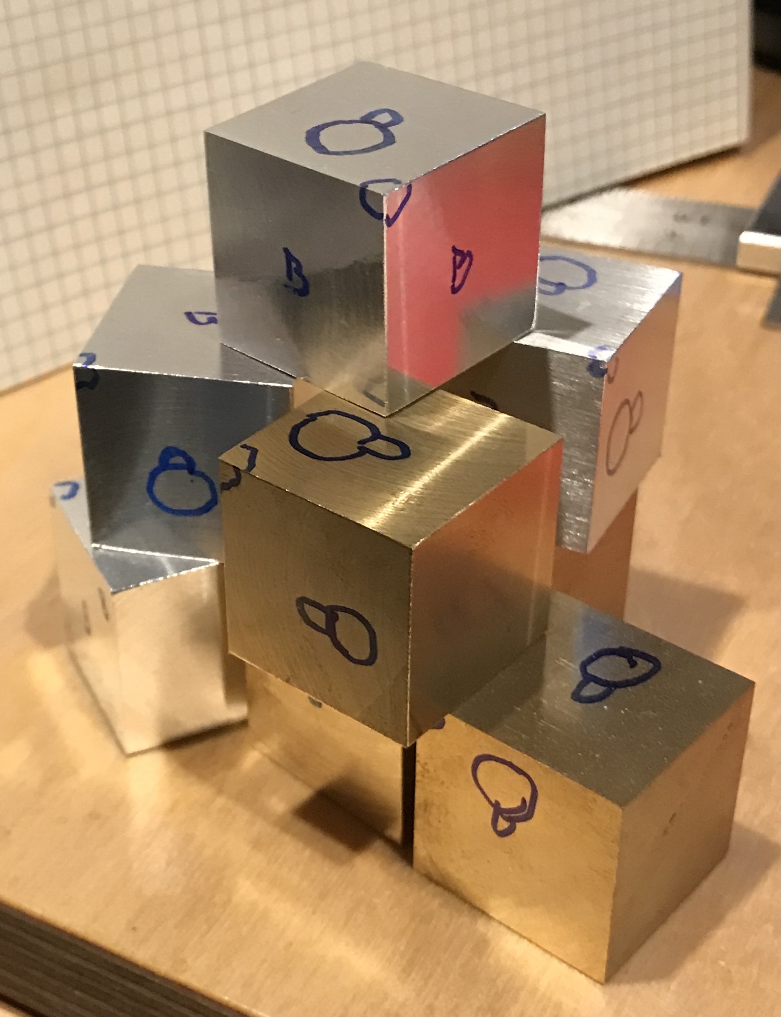
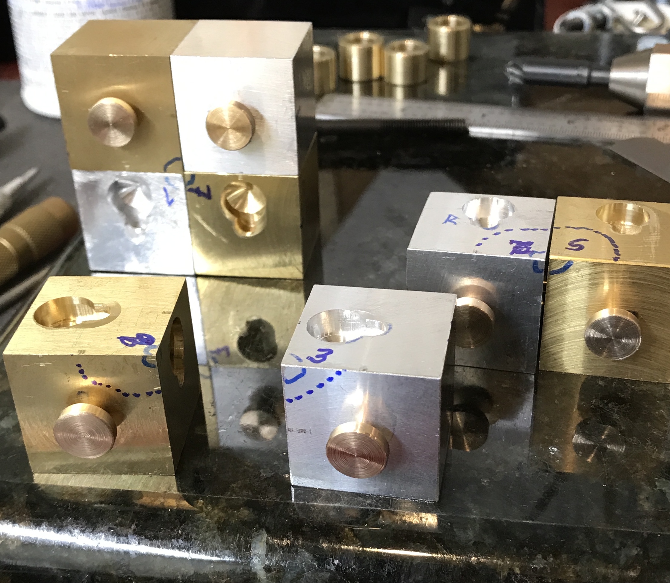
The next step is setting the length of the screws. There is enough variation that each screw needs to be fit for its hole and for the button in the other block. That requires me to know which blocks are mated. I used a picture of the two halves of the puzzle in the book to decipher the order of the blocks. This is shown below after numbering the blocks. I discovered that one of the aluminum blocks needs to have its slot remilled as none of the buttons fit in that slot.
The aluminum block with the bad slot was placed in the vise. The slot cutter was centered above the hole and lowered until it just touched bottom. It was then moved forward into the slot. A bit of material was removed. After removing the slot cutter a button easily slid into the slot. Most of the buttons stuck part way into the slots. This was because the neck diameter was too large for the slot opening. The buttons were returned to the collet in the lathe and the neck was reduced over 0.08-0.10" with the parting tool in two or three passes. All of the buttons now fit in the slots.
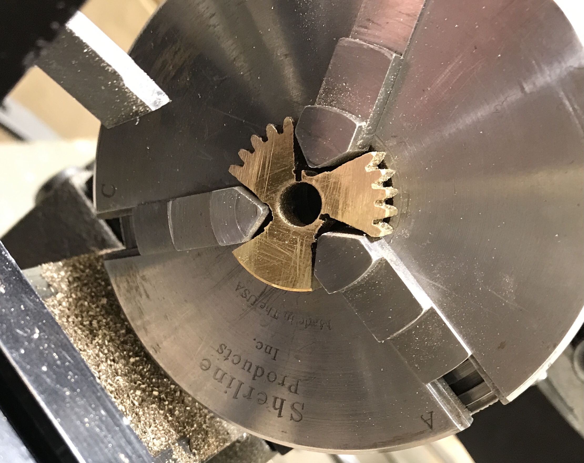
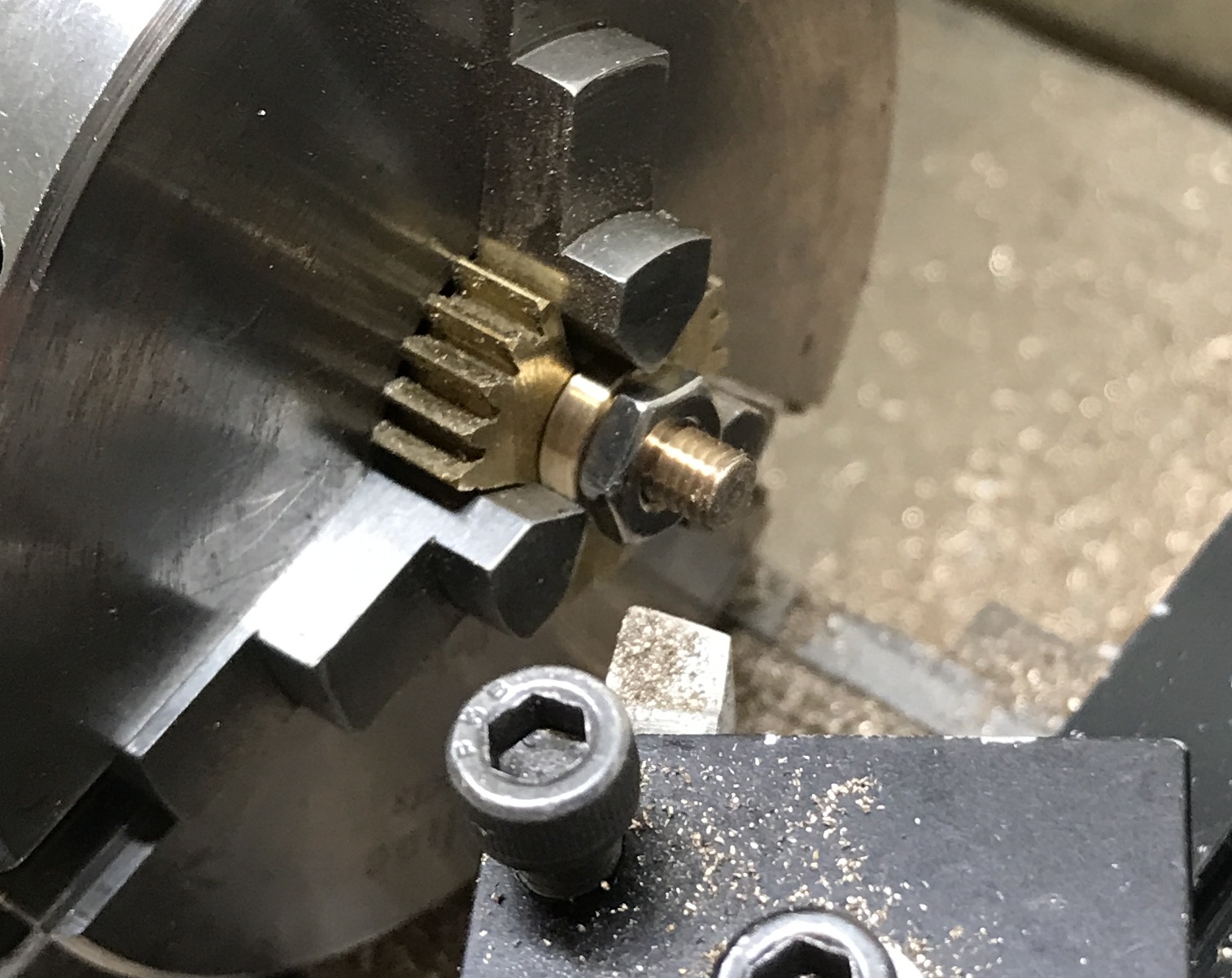
In order to reduce the length of the screws, the buttons needed to be held in the three-jaw chuck. A spider was made for the three jaw. A scrap from a failed gear was used. Three lines were marked at 120° increments by eye. A circle was scratched with the scrap in the lathe about 3/16" from center. Three holes were drilled through at the intersections of the lines with a 0.150" drill. Six lines were sketched from the outside to the sides of each hole. A hacksaw was used to make cuts down these lines to the holes. After some cleanup the lathe spider was finished. Pretty rough, but works well.
The blocks were all aligned and further marked so the buttons could be tailored for each individual pair of buttons/slots. A button was screwed into a hole. The button was inserted into its matching slot. The gap between blocks was approximated with feeler gauges. The button was then placed in the lathe against the spider and the measured amount was removed from the end of the screw. A nut was placed on the screw before reducing to clean up the threads. This was later found to be unnecessary as a 10-32 die worked more efficiently.
After all of the buttons were fitted to their mating slots the entire cube could be assembled. Two buttons required further adjustment. Fitting the final four buttons into their mating four slots was straightforward, but pushing the cubes into their final positions is tight. I will leave it this way. One, the cube stays together. Two, it is a little more difficult to determine how to get the two halves apart.
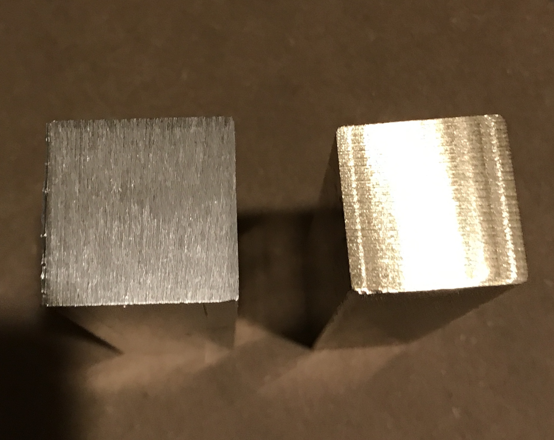
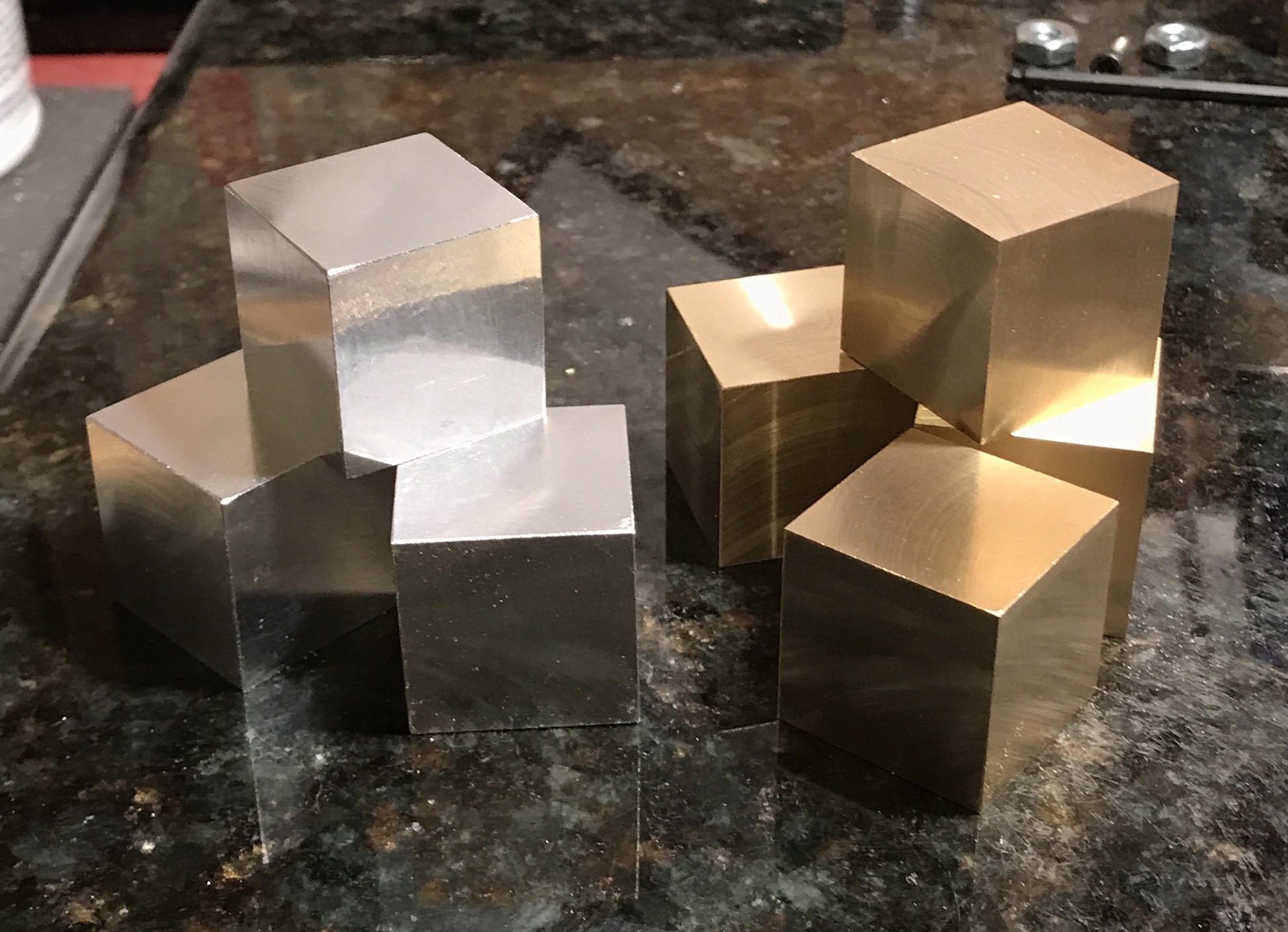
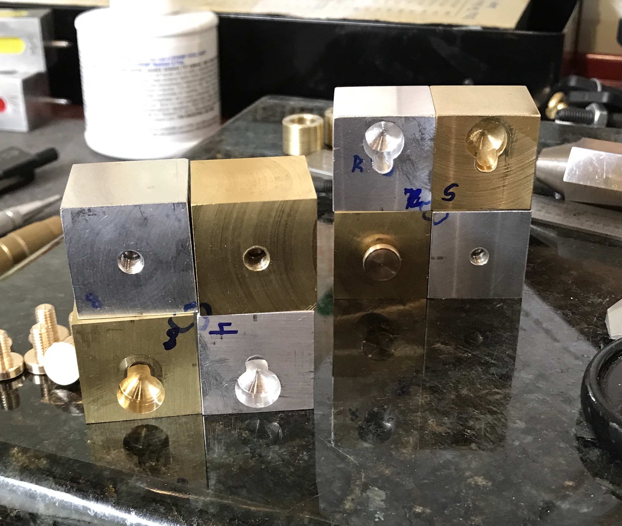
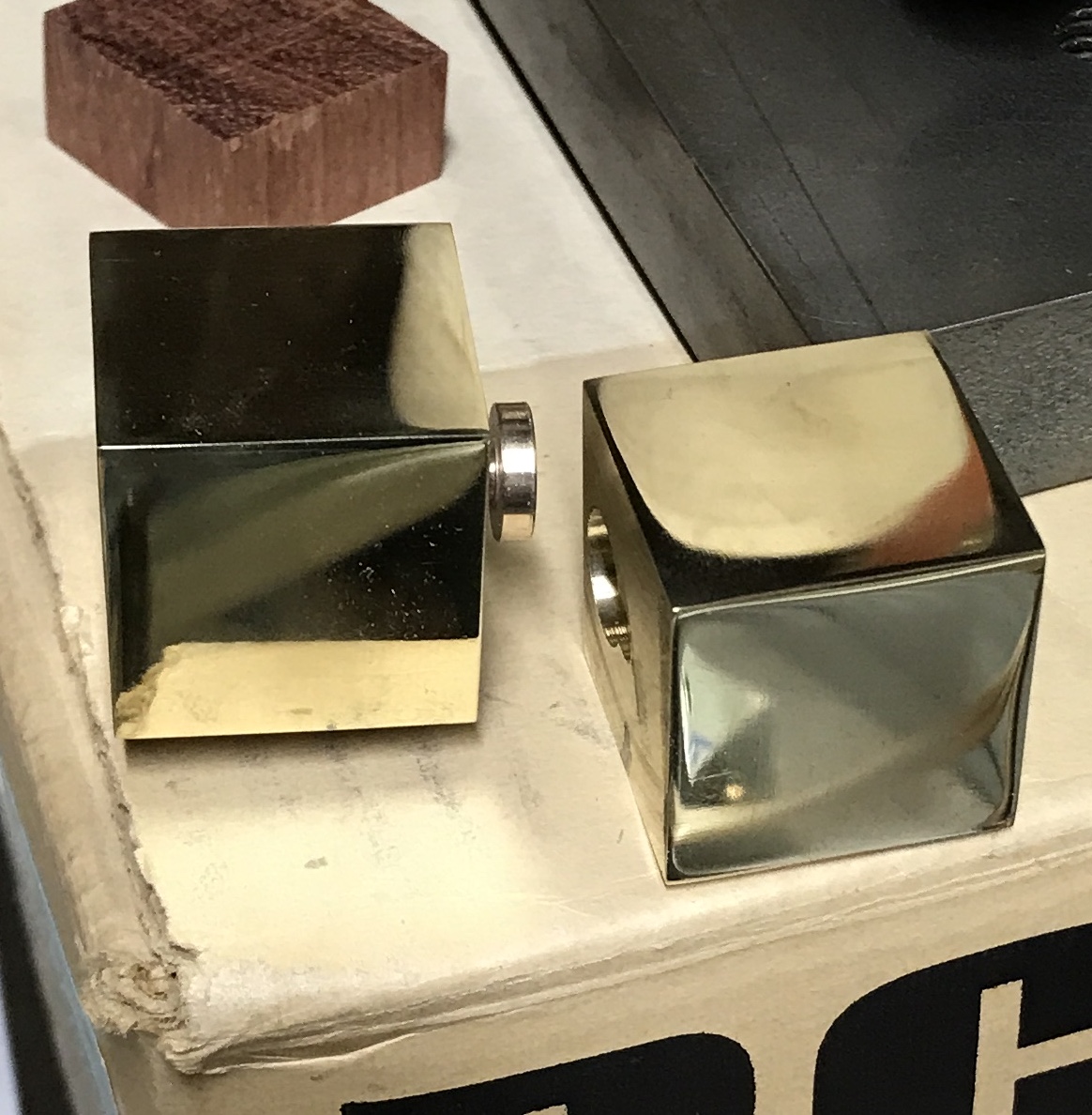
The cubes were polished starting with the brass cubes. The three outer faces were sanded from 400 to 2000 grit. The three faces on each cube were then polished with red rouge. The first two polished cubes are shown below. The remaining two brass cubes were polished as well after the same sanding process. You can just tell in the cube on the right that I am struggling with polishing. The edges of that cube are fine, but the center is still slightly cloudy!? I polished the center for some time and can't seem to get rid of the cloudiness.
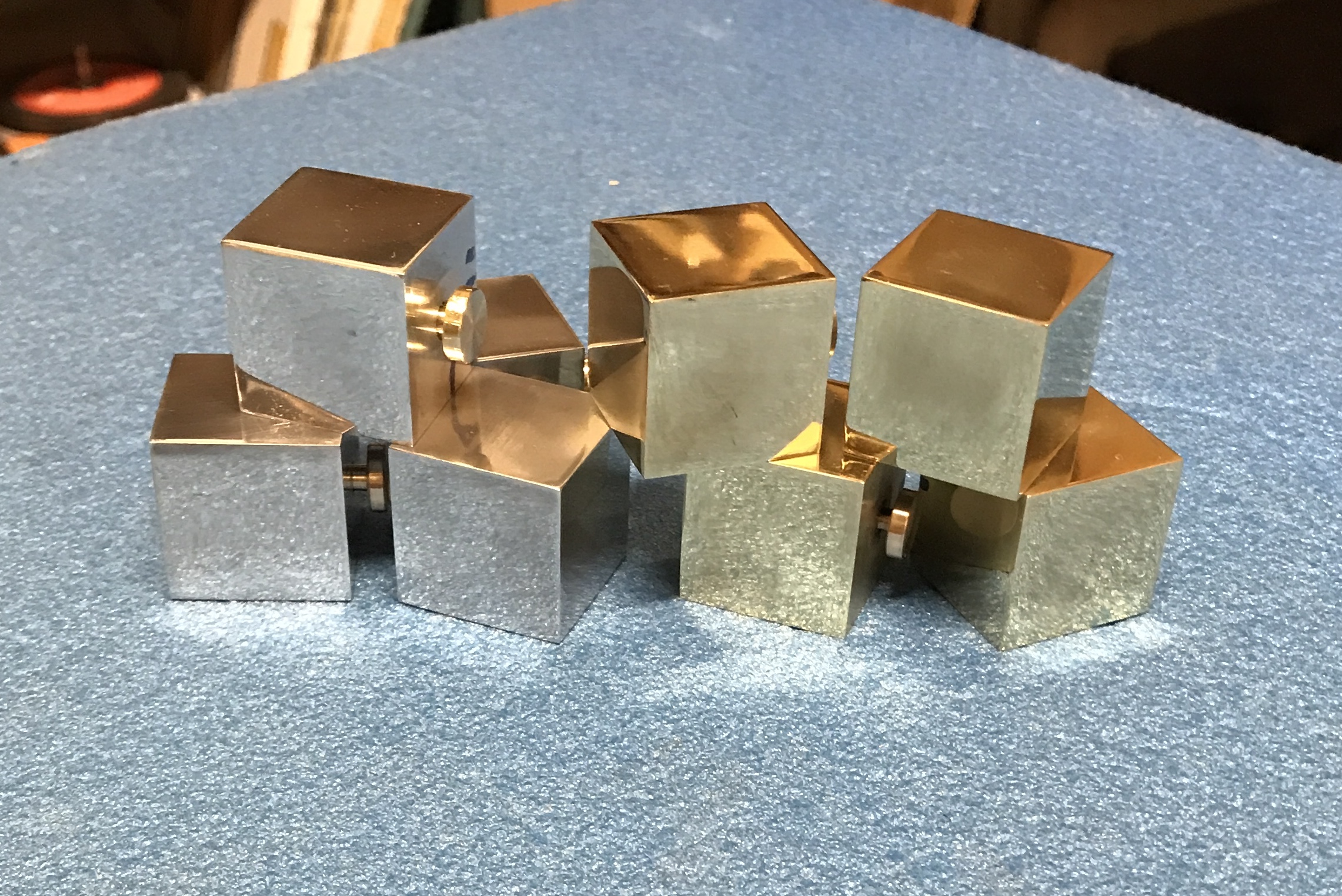
Three sides of the aluminum cubes were sanded from 400 to 2000 grit. They were then polished with white rouge. I got a better finish with the aluminum. The four edges of each face were polished and the face center was polished from all four directions. A new charge of rouge was added prior to each face. The eight polished cubes are shown below.
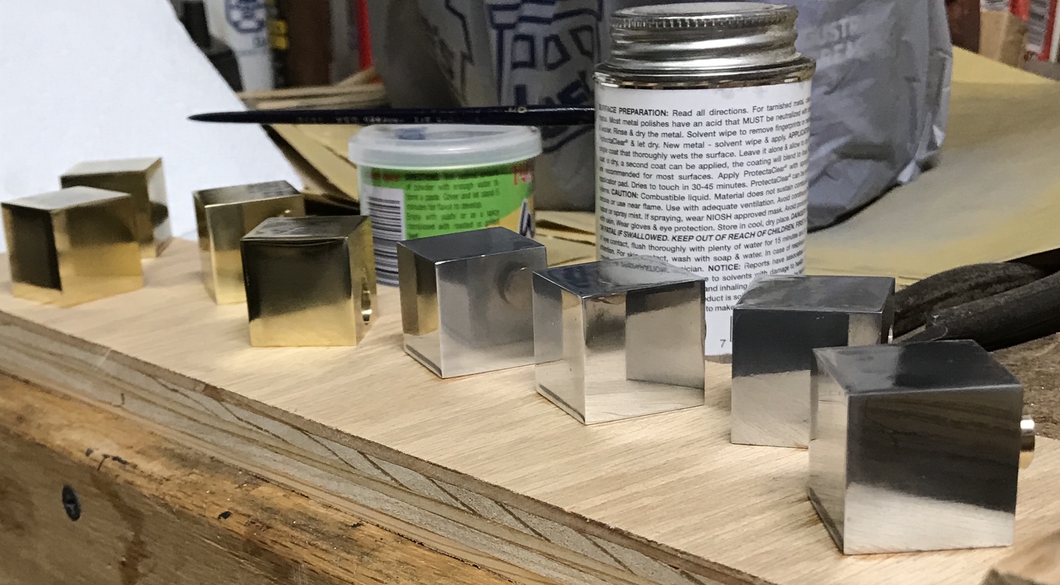
The polished faces were neutralized with a weak NaHCO3 solution. The cubes were rinsed with water and wiped with acetone on a paper towel. The polished faces were then painted with the Protecta-Clear. After drying they were painted with a second coat. The cubes after one coat are seen in the next photo.
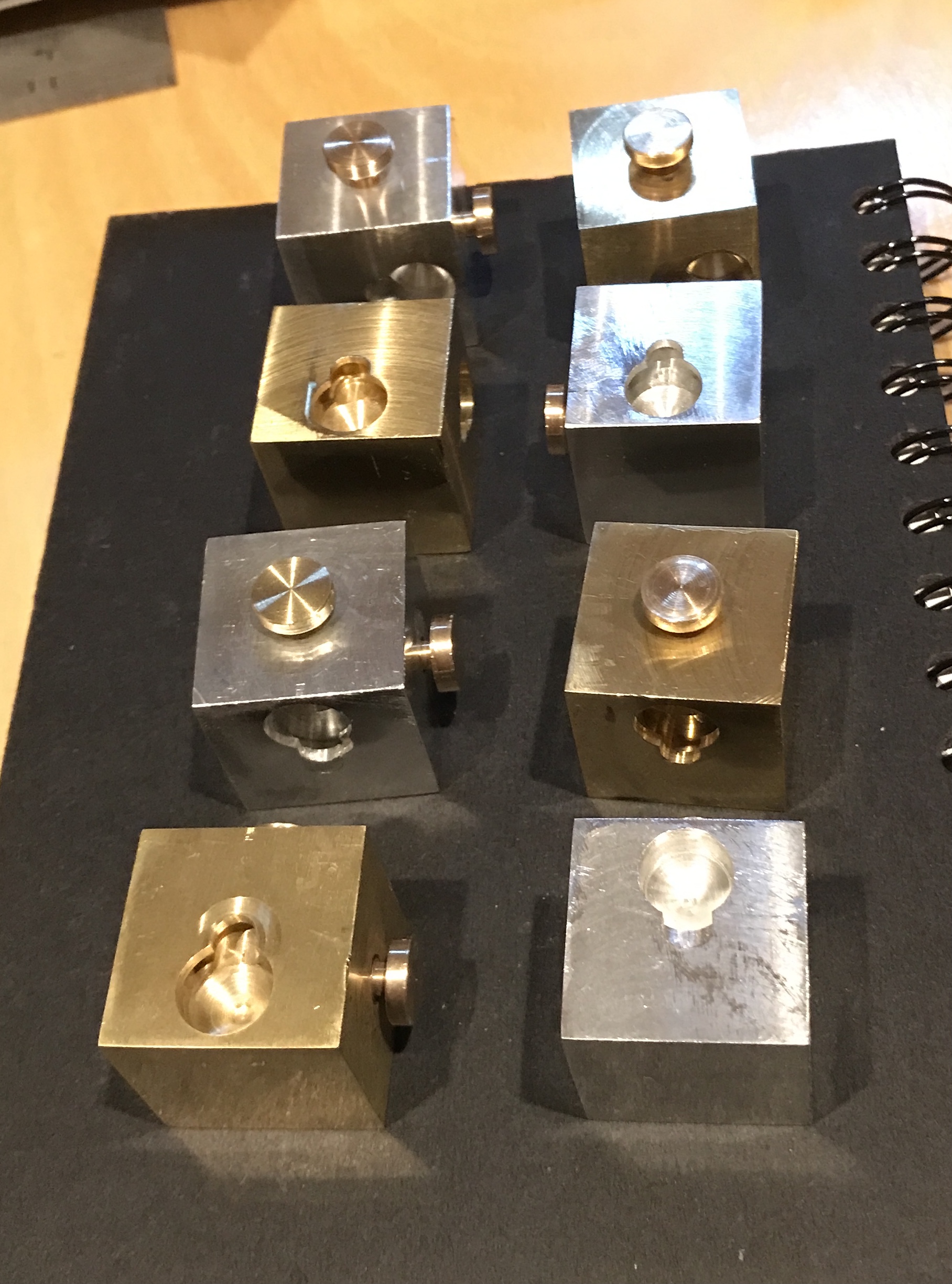
The Sharpie marks were wiped off with a little acetone after letting the clear coat dry overnight. The buttons were removed one at a time, a drop of Loctite was placed in the threaded hole, the buttons were screwed back in place. A photo of the assembled cube is shown below alongside a photo of the eight completed sub-cubes. Ran into trouble putting it together after gluing the buttons in place. One aluminum cube was just too tight. After lengthening the slot in its mating brass cube as the aluminum cube did not want to go deep enough there was still a barrier. The top of the slot was then reduced and now the cubes go together smoothly.